Machine translation from Dutch to English of this fine page with DeepL translate: http://members.home.nl/radiomorningstar/ Culprit: Boomer Dog. Links may not work
Wayback Machine archived page:https://web.archive.org/web/20200309143146/http://members.home.nl/radiomorningstar/laagverm.htm

The art of LPAM
Broadcasting
Broadcasting
Low power & Low profile, the best way to stay on the
air
|
| Do it with low power, a lot of fun with little power.
Broadcasting Low power & Low profile, the best way to stay on the air
Pirate transmitters today look like cold war tools, Hectowatts, Kilowatts, Megawatts.
Tubes from TH100's via 813's or 833's to 4CX3000 and heavier.
On this page I will show that it is also possible with a little less power, below 5 watt carrier power or QRP transmitters.
On short wave, but also medium wave, you can sometimes achieve incredible results with a few watts, even more so with milliwatts.
I have already received many reception reports from listeners at distances of 100 to 1000 Km with powers well below 1 watt.
Recently the distance to Enschede, Berlin with only 50 milliwatts in the 48 mtr band, note this was in AM!
Not only short wave, also on medium wave it is well possible with a half watt or so a medium city to provide sound.
Actually nothing new, the oldtimers in the 50's were usually "on the air" with an AL4, an EL3 or an EL 84.
And these were self oscillating single tube transmitters where really no more than 2 to 3 watts of carrier power came out and yet there was with this
small capital they were regularly reported here from Twente to Drente, Groningen and Friesland. A few months ago I received a report
from Moscow, no not with a large transmitter but with my little transistor transmitter with a single IRF 510 in the output stage, something of 12 watts carrier wave.
Also on 48 mtr once heard in Belgium with a 2 watt transmitter and my 80 cm Magnetic Loop Antenna in the attic. And with 400 milliwatt a S9+20
signal in Amsterdam and even in England or at the Austrian border is not an exceptional event.
So don't tell me you have to fire up at least 500 watts to be heard, because I just know it's not true.
I'm going to describe a number of small transmitters here, some of which are already usable with a 9 volt battery as a power source.
|
How does LPAM sound: Here a recording made via the SDR at 5 Kilometers distance from a 200 milliwatt LPAM transmitter:
As antenna a wire of 10 mtr length is used at about 8 mtr height in the garden. |
 |
| Here's another recording, this was with about 1 watt at 6300 Kc, this recording was made in Northern Italy. |
 |
|
Here's a nice recording, also this is received on the SDR receiver. The transmitter used had an output power
of only 75 milliwatts carrier wave. The audio processing is here at 50 dB compression, attack 100 mSec and filter cut off.
4500 Hertz |
 |
And this recording proves that it can be done with even less, power is here turned back to 5 milliwatts!
Although there is no audio compression applied now, the signal is still audible at 5 km away
SDR receiver |
 |
| |
|
| |
|
|
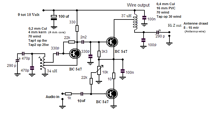
Here the schematic of the transmitter used in this experiment, 3 transistors of type BC 547 are used.
But also other low power transistors can be used for this.
As a power supply I used a 12 volt adapter, but even on a 9 volt battery this LPAM transmitter still works.
The 10 K potentiometer is used to set the correct operating point for the modulator, measure the voltage between the two transistors and adjust the voltage.
With the 290 Pf tuning capacitor you can set the frequency with the second tuning.
Capacitor adjusts the antenna for maximum radiation
And here's a picture of this baby transmitter
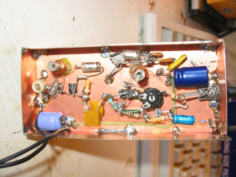
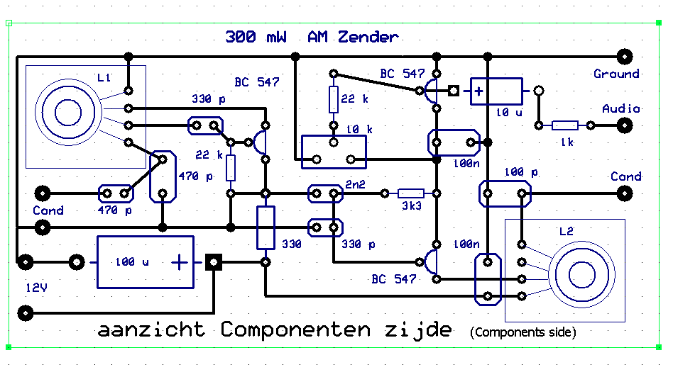
Although I built this proto type according to the
"Dead Bug" method, you can do it very well, too.
on a PCB or a piece of perf-board
, I just drew a print layout for this
just remember that this layout was drawn from the
top view
,
for the wiring side, you have to rotate the drawing 180°.
the plate used is 10 x 5
cm
|
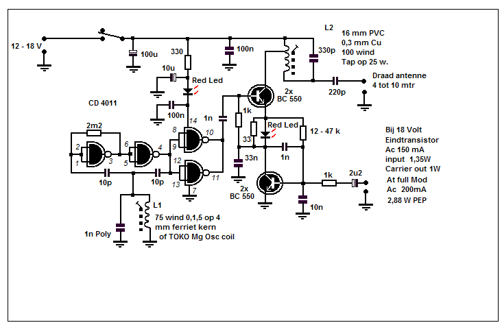
And here's a second LPAM transmitter, here's a...
CD 4011 as an oscillator
.
on 18 volts I got around 1 watt out.
 |
Broadcasting in enemy territory that's what pirates are actually doing, make sure you stay invisible, that goes for the antenna.
The above low power transmitters can have a considerable range if you use a good antenna, high and long.
I myself use an Inverted L antenna of over 20 mtr 8 mtr up and then 12 mtr horizontally ... Sometimes, however, you don't have the possibility to use such an
antenna because there is simply no space or you don't want to betray the transmitter's location at all by using a visible and attention grabbing antenna
construction. In that case, you'll have to resort to "invisible constructs" wires in an attic, stretched over a perola, invisible,
stretched out on a balcony or along a fence. Or of course the acclaimed Magnetic Loop Antenna which can actually be placed anywhere and even
doesn't need height. Problem is, of course, that these antennas have a low efficiency, on average. Emitted signals from these antennas
are about 10 dB lower than those of a good outdoor antenna. There is only one thing to do against that, make sure that the transmitter signal is about 10 dB stronger.
Fortunately, it is not so difficult for LPAM to boost the signal 10 dB. To do something like that with a 100 watt transmitter you will already have a huge
Kilowatt, but for a 300 milliWatt transmitter a 3 watt output stage is enough to achieve the desired 10 dB.
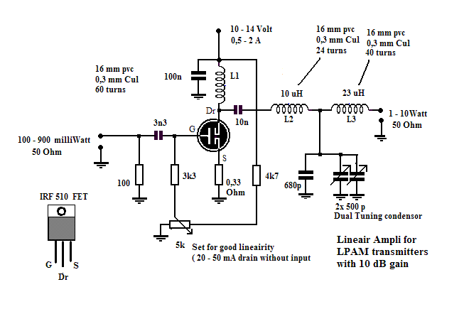
In the output stage below I used an IRF 510 FET which, depending on the control, can deliver a power of 1 to 10 watts.
More than enough to achieve similar results with a camouflaged antenna as with the "bare" transmitters and a good outdoor antenna.
The output stage is in class B
 |
| |
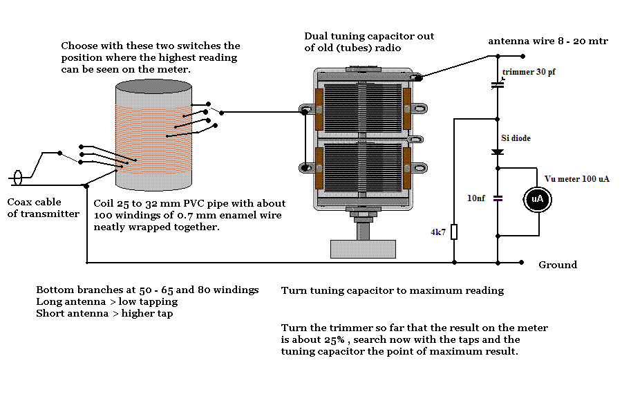
| Here are the schematics of an LPAM antenna tuner,
usable up to about 5 to 10 watts, with this tuner
just about everything can tune as a transmitting antenna
ranging from a long wire antenna between the houses,
to a spiral mattress, clothesline, gutter and a wire
of one meter or 8 The tuning capacitor must be completely
insulated, e.g. on a piece of perspex, Plexiglas etc.
Don't use metal tuning knob.
|
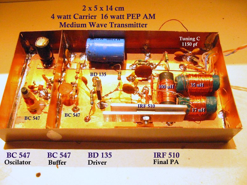
My next project, not really LPAM anymore but still QRP.
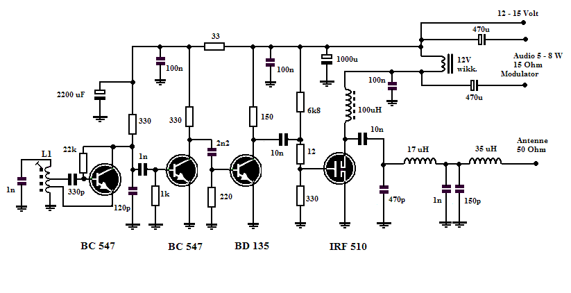
In this transmitter I used an IRF 510 as an output fet, this is driven with a BD 135 and two BC547
as Oscillator and Buffer lineup. At the output I used the notched T filter for adjustment to 50 Ohm. A T filter is known for
good harmonics suppression, the second harmonic is already over 30 dB attenuated. This transmitter does not have its own modulator but is modulated
by a small amplifier, a power of 5 - 7 watts is more than enough. Modulation by means of an AF choke and two electrolytics, for the choke I used the secondary winding of a small power supply transformer, mine was for 12 volts 0.7A but any small transformer from 6 to 18 volts is usable.
With this transmitter I got an output of about 4 - 5 watts carrier power and with the amplifier I used (one from a computer soundcard).
I reached 16 watts of PEP at full modulation. As power supply I used a 12 volt 2A switched adapter. The advantage of these switched adapters is that
they provide a good stable and buzz-free voltage. With this transmitter and 8 mtr antenna wire, stretched back and forth on the balcony of the bedroom the
signal on the SDR receiver 5 km away was already a large S9+5 dB. The antenna wire was equipped with an extra coil to bring it into resonance
on the transmission frequency.
Here are the schematics and the construction of this small QRP transmitter
Here's a recording I made through the SDR receiver, this
was with the 8 mtr wire antenna on the balcony 

Though we live in the twenty-first century and most of us only know the Lamp (valve, tube) as that thing we use
in the dark when reading the newspaper, "Lamps" used to be used in radios, televisions, amplifiers and transmitters.
The following diagram is especially for those Oldtimers who still know what was meant with a "Radio lamp" and this piece of
technology from a gray past. And for the newbie's among us a unique opportunity
a glimpse into a long-forgotten piece of radio history.
In the old days, the life of a radio repairman used to be simple. When another report came in saying "my radio doesn't work" you were sent to the customer with...
A box of spare bulbs, a pair of cutters and a screwdriver, a voltage detector and a universal meter.
I can still remember that time, I always took the famous standard lamps, in a suitcase on the back of the bike; the transport was in those days also easy.
AZ1, AZ4, AZ 41, EZ80 and 81 for the power supply, then the most commonly used "end lamps" AL4, EL3, EBL1, EBL 21, EL41 and the EL 84. Mixing tubes were also often gone to the eternal hunting fields, so an AK2, ECH 3, ECH 21, ECH41 and an ECH 83 were also definitely not missing in the repair case. Furthermore, a lot of regulators, then a few high-frequency and low-frequency pentodes AF3, EF9, EF6, EF22, EF 41, EBF 89 and with the coming
of the FM radios of course the EC 92, ECC 85 and not to forget the famous EABC 80. Besides those, E tubes of course, also the necessary U tubes
for the then still widely used radios without power transformer with the 220 volt directly on the chassis, the earth leakage switch did not yet exist, hence the voltage finder.
Then a handful of capacitors because especially the Wima's and not to forget the famous "negro locks" or those black tar capacitors, plus a handful of resistors, just in case. That's all you needed to bring every radio back to life.
Somewhere in a forgotten corner I came across a few tubes, a box with PCF 80's EF80's, a few EL 84's plus a few matching tube sockets and underneath the bottom of the box also a handful of enormous resistors and capacitors, yes those were big in those days.
Then I couldn't resist to build a transmitter with them. I started from the well known "MOPA" principle,
a Master Oscilator and a Power Amplifier, however with only 1 tube, the very universal ECF 80 or PCF 80, a tube what in the late 50s, early 60s was used
for many different applications and a very nice tube to build anything and everything. In the old days, a long time ago, I got that ECF 80
even to build a 27 Mc tranceiver, the triode part as super reg detector / oscillator and the pentode part as LF amplifier,
fed from the vibrating inverter of a (tube) car radio actually managed to connect with two of those things up to a kilometer away or so, between two cars.
The LPAM transmitter which I have now built still delivers a 3.5 watt carrier power on medium wave and can be used without any problems.
with the adjustable power supply which can provide an anode voltage from 50 to 250 volts, the power is adjustable from 0.3 to 3.5 watts and at full power.
I get a large S9+10 db on the SDR receiver.
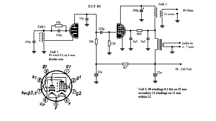
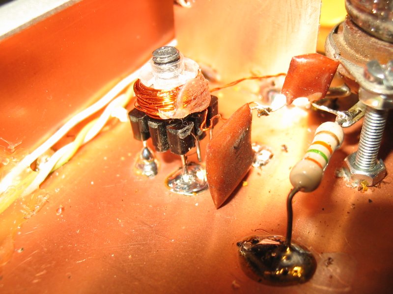
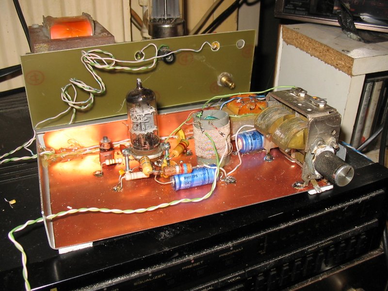
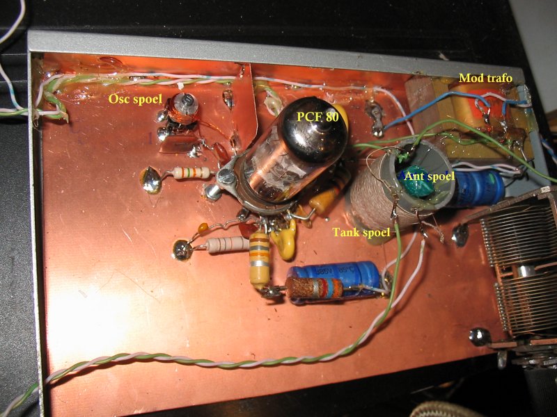 Click on the images to enlarge
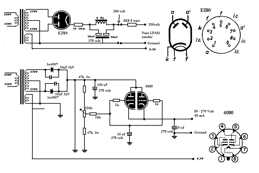
Then here is the power supply diagram, the top diagram is the standard diagram as used in most radios of the fifties and sixties.
with an EZ 80 or EZ 81, this type of power supply usually provides a voltage between 340 and 370 volts, our LPAM transmitter must therefore be connected via
a resistance to lower the voltage
The second scheme is the adjustable power supply I use, which can provide an adjustable voltage between 50 and 350 volts at a maximum of 60 mA.
The used tube is a high current double triode of type 6080, these were used in Tektronix osciloscopes as a control tube.
The
next project, Power Line Communication, Current Carrier
Transmission,
Mag Loop and other invisible antennas
More LPAM tinkering
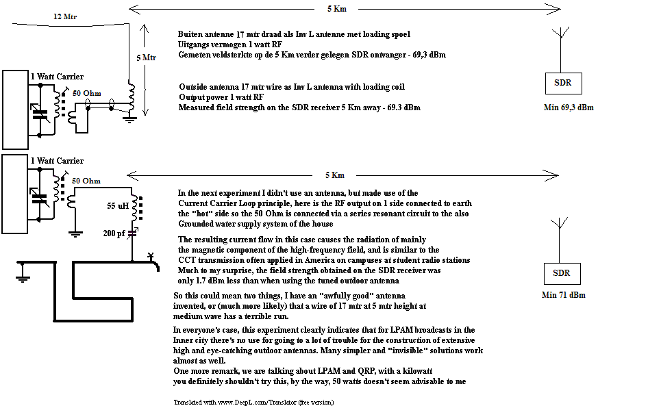
After generating the transmitter power it is now the antenna's turn. Because I am in the blessed position that there is a beautiful SDR receiver on the web fairly close to my location, this gives me the opportunity to make all kinds of fun antenna tests. With the current use of the mains as transmission medium (PLC applications) and the old Current Carrier system I decided to put out the enormous power of my 1 watt transmitter to see if there is anything on the SDR. Imagine my surprise that even without the outside antenna but with the RF pumped into the water pipe, the signal on the SDR came through almost as strong as with the tuned wire antenna. What has become clear in these experiments is that, especially for LPAM, you don't always need a large outdoor antenna. A well known example of this is the old cordless phone sets from the 70s. Here the handset used a transmission frequency somewhere in the 40 - 70 M/c while the base set was operating in the area of 1700 - 1600 Kc , where the transmitting signal was also Carrier Current and used the mains as an antenna. Although this transmission signal usually went no further through the wiring than the mains in the house itself due to the damping of the coils in the electrical consumption meter, the signal with a good receiver was sometimes good to receive up to several kilometers away despite the fact that the effective output power was sometimes only a few tens of milliwatts. With this in mind I decided to do the ecxperiment shown below. The 1 watt signal from my test transmitter was audible on the SDR receiver of the UT Twente at a distance of more than 5 km.
However, it is advisable to perform these kinds of experiments only with LPAM or QRP transmitters, signal from higher power can cause huge disturbances in our modern electronics. So do not under any circumstances try to release the power of that huge SK 50 or VT cabinet on the AC mains but stay below 5 watts.
| Here is a recording made with the SDR receiver of the signal from the 1 watt transmitter loaded with the earth / water pipe loop as on the
bottom drawing |
 |
A good working tuner for carrier current
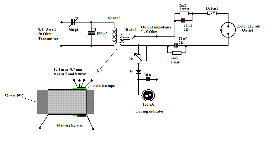
This is a tuner for Carrier Current broadcasts. Because the high frequency impedance of the mains is very low, in most cases even
under the 1 Ohm, we need to transform the 50 Ohm transmitter output impedance down, for this I use the following circuit.
With the two tuning capacitors we find the right resonance point, the tuner is usable from about 1000 to 1800 Kc. It is also usable
for the area below 1 Mc but then the primary coil should be 70 - 85 windings instead of 60 windings
Remember that the secondary part is attached to the 220 volt of the mains, so use good separation capacitors, I've got one here.
Two 2 kilovolt types used, the 2m2 resistors ensure that no voltage remains on these capacitors after disconnection.
A charged capacitor can give a big shock if you touch it because of these resistors any remaining voltage will leak out immediately.
Using the tuning meter it is easy to tune the tuner to the transmission frequency with the two capacitors, with the
taps on the secondary coil first select the highest output and then adjust the two tuning capacitors to maximum.
More small transmitters
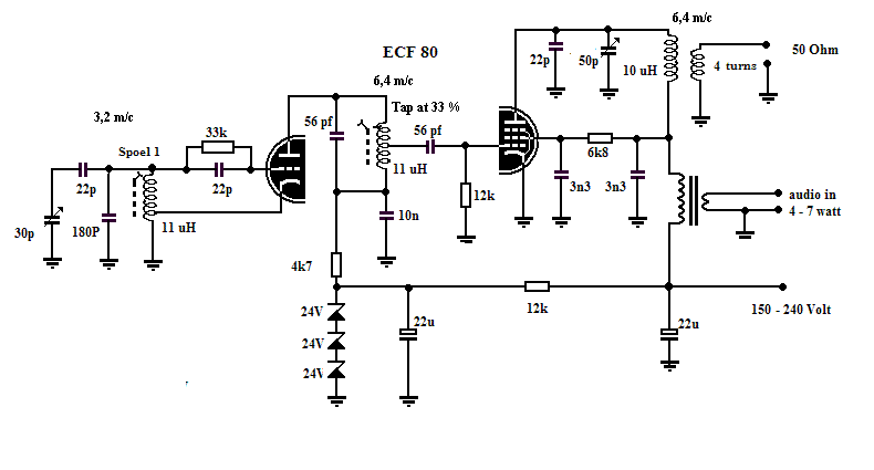
Here two more small transmitters, first a small shortwave transmitter for the 48 Mtr band, here I started from the first ECF 80 MW transmitter.
I ran the oscillator at 3.2 M/c and tuned the anode circuit to the second harmonic 6,4 M/c. This still provides sufficient voltage
to fully transmit with the pentode part, here also a 2.5 to 3 watt output is achieved, enough to be heard throughout Europe.
To improve the stability I stabilized the power supply of the triode part at 75 volts by means of three zener diodes. With this transmitter a good
signal achievable between 6.2 and 6.5 M/c
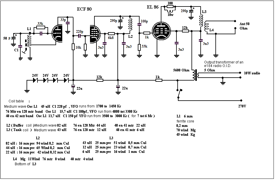
The second transmitter is again for medium wave, again I used the original ECF 80 scheme, only here the pentode part
is used as a buffer/driver and as an output stage a solid EL 86 is used to achieve an output of more than 7 to 9 watts on MW.
If you like a solid signal and you don't want to work with high power tubes at the same time, this transmitter is a good compromise between LPAM and MPAM.
with a good antenna, a range of 25 - 35 Km is achievable.
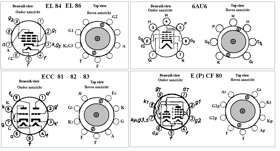
Connections of the used tubes in bottom and top view
For a tube man, of course, piece of cake, but in today's semiconductor era, it may take some getting used to, the connections from
ICs are drawn from the top in a counter-clockwise direction, the connections of tubes are drawn from the bottom in a clockwise direction.
That is of course very handy, if you mount the tube feet on a chassis you count the connections clockwise.
However, if you use the old 1930's mounting method like I do, you'll need to count the connections counterclockwise just like semiconductors.
In the old days, and I am indeed talking about the time of around 1930, it was customary to use wood screws for the different parts,
mounting them on a shelf and then installing the wiring in between. I've also used this way, only I don't use any
board but solder (or screw) the feet etc. on a piece of blank copper board, that saves drilling a lot of holes.
Only now it is sometimes difficult not to make mistakes with the "rear front" count of the tube connections. That's why I only have one
Bottom and top view drawn from the tube connections of the tubes used, hopefully that makes mounting somewhat easier.
Two tubes, 6
watt for MW, 76 or 48 mtr
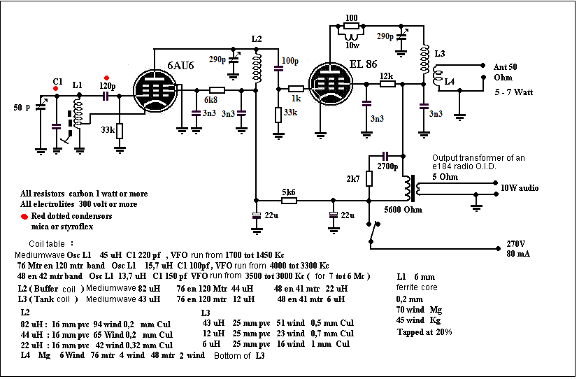
The next transmitter is also a two-stage MOPA transmitter, only 2 tubes have been used here. As oscillator I used a 6AU6.
but with an EF 91, EF 92 or similar tube it works just as well. As the second tube I have chosen for the EL86
An EL 84 will work, only I got a little less power. With the EL 86 I got a good 6.5 watts in the test circuit.
with an EL 84 the achievable power was somewhere between 5 and 5.5 watts . Remarkable was the stability of the VFO , aproximately less than 100 hertz during warming up after which the frequency remained constant within 10 - 15 hertz.
The schematic and the pictures clearly show the construction, I also added the coil data for both MW and multiple SW coils.
On the 42 and 48 mtr band the oscillator also works as a frequency doubler, the grid / cathode part oscillates at half frequency in the
3 to 3.5 Mc band, the anode is then tuned in the 6 - 7 Mc band with enough drive left to drive the EL 86 properly.
| Here a recording made via the SDR of this 6 watt transmitter, in this test the sound processor is set to max.
Multi-band on compress 93%, Naband on Limit 4.3x 77.7% bandwidth at 4500 Hertz, mod depth 95% |
 |
 |
|
| Above a detail picture of the acillator coil and the
50 PF tuning capacitor |
|
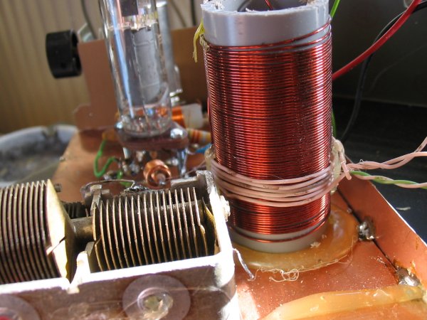 |
|
Above we see the tank coil, at the bottom the
5 windings for the 40 Ohm connection
The tuning capacitor is a philips type from a 50 -
60s radio |
|
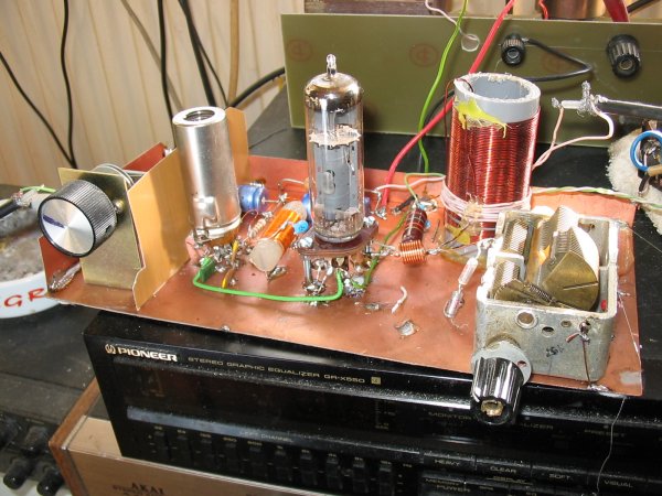 |
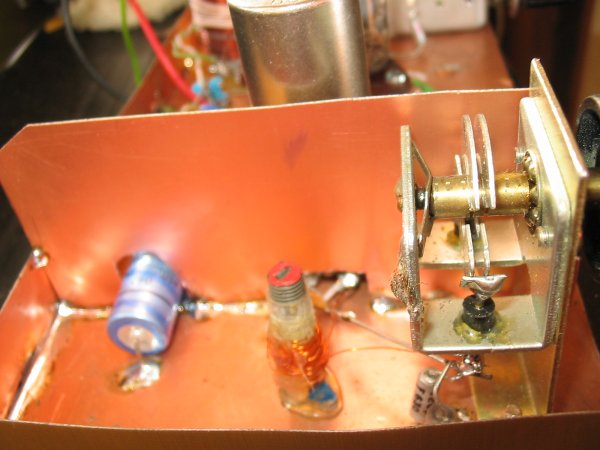
Here the transmitter in front view, far left a
separate "booth" for the oscilator coil and
fine adjustment capacitor with which the frequency is tuned approximately 30
Kc
The 6AU6 sits in a shielded tube holder |
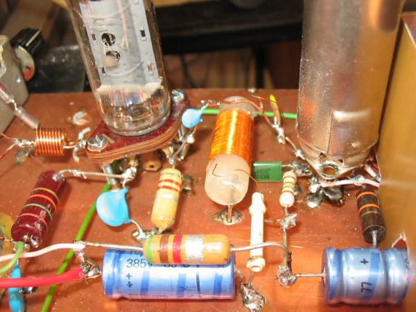 |
Here a detail picture of the circuit between the
two tubes, clearly visible coil L2, wound on
a piece of an 11 mm glue stick
left of the EL 86 still clearly visible is
the parasite stopper, a 10 windings coil over a
100 Ohm resistor |
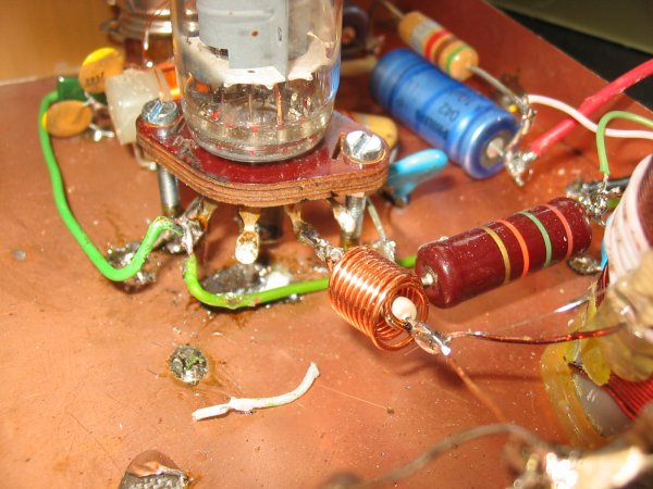 |
Here again a clear picture of this
parasitic stub, this must not be missing in any output stage,
with or without you will not
notice any difference at first, but if you look at the output signal
on a spectrum analyser without this filter,
the signal doesn't look good any more and there are
various spikes to be seen, sometimes up to over 500 M/c |
| |
|
| |
|
| |
|


