C-QUAM test transmitter
by Oldeurope
In conventional externally excited AM transmitters, an unmodulated carrier
comes from the control transmitter. In the transmitter end stage, the carrier
is provided with the audio sum signal, i. left plus right stereo channel,
monophonic amplitude modulated.
The C-QUAM transmitter differs from conventional AM transmitters in that the
control transmitter delivers a phase-modulated C-QU carrier instead of the
unmodulated carrier.
C-QUAM can therefore be used for all externally excited AM transmitters.
The transmitter output stage, in which the amplitude modulation takes place and
the control transmitter can still operate with good efficiency also non-linear
(for example, in operating class C).
C-QU is a phase-modulated carrier signal. If AM is modulated with suppressed
quadrature (90-degree) carrier, quadrature modulation QU is obtained.
The difference signal, left minus right stereo channel, is
quadrature-modulated.
If you add the AM signal to this, you get QUAM.
If you limit QUAM, C-QU remains.
C-QU comes from the controller.
If C-QU is amplitude-modulated, then C-QUAM.
A finished C-QUAM signal would have to be linearly amplified like a finished AM
signal. Therefore, C-QUAM control transmitters have a stereo LF input, a
mono-LF output for the modulator and a C-QU-HF output for the transmitter
output stage.
C-QU can also be generated directly
with phase modulation. So I do this with the following described C-QUAM test
transmitter:
Block diagram of the C-QUAM transmitter
Differenzsignal gewinnung - Difference signal generation (and NRSC filter)
Pilot generator, Oscillator, Phase modulator, Amplitude modulator, Ferrite loop antenna
A few links that serve the understanding:
The Tech Zone with additional links
http://www.amstzone.org/
C-QUAM
http://www.wa2ise.com/radios/amstrjb.html
This one definitely brings an Aha experience
http://electronbunker.ca/eb/AM_StereoXMTR.html
Therefore, by means of phase modulation, a two-sided band signal with carrier
in quadrature can be generated. pdf, page 8 of 18
(Not Found)
RMorg Overview of the AM Stereo systems in general. pdf at the end of the text
http://www.radiomuseum.org/forum/stereo_auf_mittelwell...
AM preemphasis pdf file see pages 4 of 24 below, 5 of 24 and 10 of 24.
NRSC-R10.pdf
I do not agree with everything. For this purpose, the descriptions of the
modules of the transmitter are more important.
C-QUAM Lageplan der einzelnen Baugruppen - C-QUAM Map of the individual assemblies
LMC6484 - CMOS Quad Rail-to-Rail Input and Output Operational Amplifier
Begrenzer verstärker 4046 - Limiter amplifier section in 4046 PLL (PLL not used)
HF Endstufe - HF output stage
Modulationsanzeige - modulation display
Pilotton Oszillator und Teiler 4060 - Pilot tone oscillator and divider 4060
Sinusformung Pilotton 25 Hz - Sine shaping Pilot tone 25 Hz
The AM modulator and the transmitter
antenna with ferrite bar
The amplitude modulation is effected by the modulation of the operating voltage
of the output stage. Based on the classical anode screen grid modulation as
"emitter modulation", because the transmitter output stage works in
collector circuit.
Via the I-modulator, an emitter
follower, the operating voltage of 2V5DC is fed to the output stage. A 100nF
capacitor and a 47μH choke keep the RF away from the modulator.
At 100% modulation, the operating voltage that the modulator of the output
stage provides varies between 0V8 and 4V2. The modulation control LED on the
front panel goes out just before the 0V8 is reached. So the test transmitter
can easily be adjusted.
The small operating voltage
counteracts the drive of the ferrite antenna in serial resonance. The raw shows
the RF voltage profile at the antenna capacitor and the voltage profile at the
output in the balanced state. In the simulation I have the operating voltage
from the smallest to the highest value graduated in different colors. You can
see how the antenna circuit is sucking the first harmonic (fundamental wave)
out of the square wave signal.
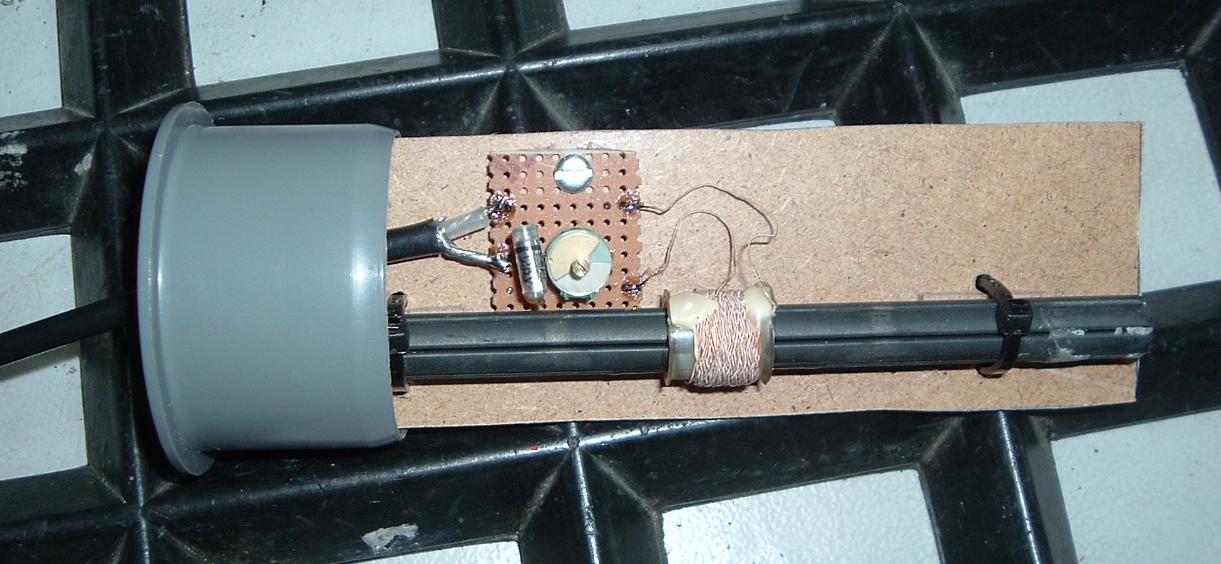
The emission via a magnetic antenna (here a ferrite bar as a transmitting
antenna) does not require a counterweight (earth).

As a result, there are no brum
problems when they are received. In order to avoid irradiation into the
transmitter, the ferrite rod is placed horizontally about one meter away from
the transmitter. The resonant circuit of the transmitter antenna is located in
a piece of HT tube.
The circuit uses the BC557C in the collector circuit. Since the control voltage
is less than the Z voltage of the BE diode, the operating voltage of the
collector circuit can be modulated.
AM-Preemphasis, Stereo-Matrix and Modulator
With the Preemphasis I tried to
approach the NRSC curve. Despite the preemphasis, it is easily possible to
place two transmitters next to each other at a distance of 9KHz without
interfering with each other. I tried it.
This works because audio frequencies over 4.5KHz in the sound frequency
spectrum are relatively quiet. They are hardly blended down in the useful
signal. Only when the neighbor is much stronger, splatters become audible.
There is therefore no need to limit the bandwidth of the audio in the
transmitter to 4.5KHz.
There are rumors that a stereo AM signal requires a higher bandwidth than a
monophonic signal and therefore can only be used there in the USA because of
the 10KHz grid.
However, in fact, the quadrature amplitude modulated signal or a corresponding
phase modulated signal is not more broadband than the amplitude modulated
signal. And at the one kiloherz more at channel distance in the USA it can not
hang also, that it supposedly only there works.
It is of course possible but absurd to broadcast a C-QUAM stereo transmitter
with 4.5KHz NF bandwidth and resulting 9KHz RF bandwidth. Even the narrow-band
stereo reception has nothing to prevent.
Workupload preemphasis, sum and
difference signal matrix and I-modulator LTspice
25Hz pilot tone generator for stereo recognition
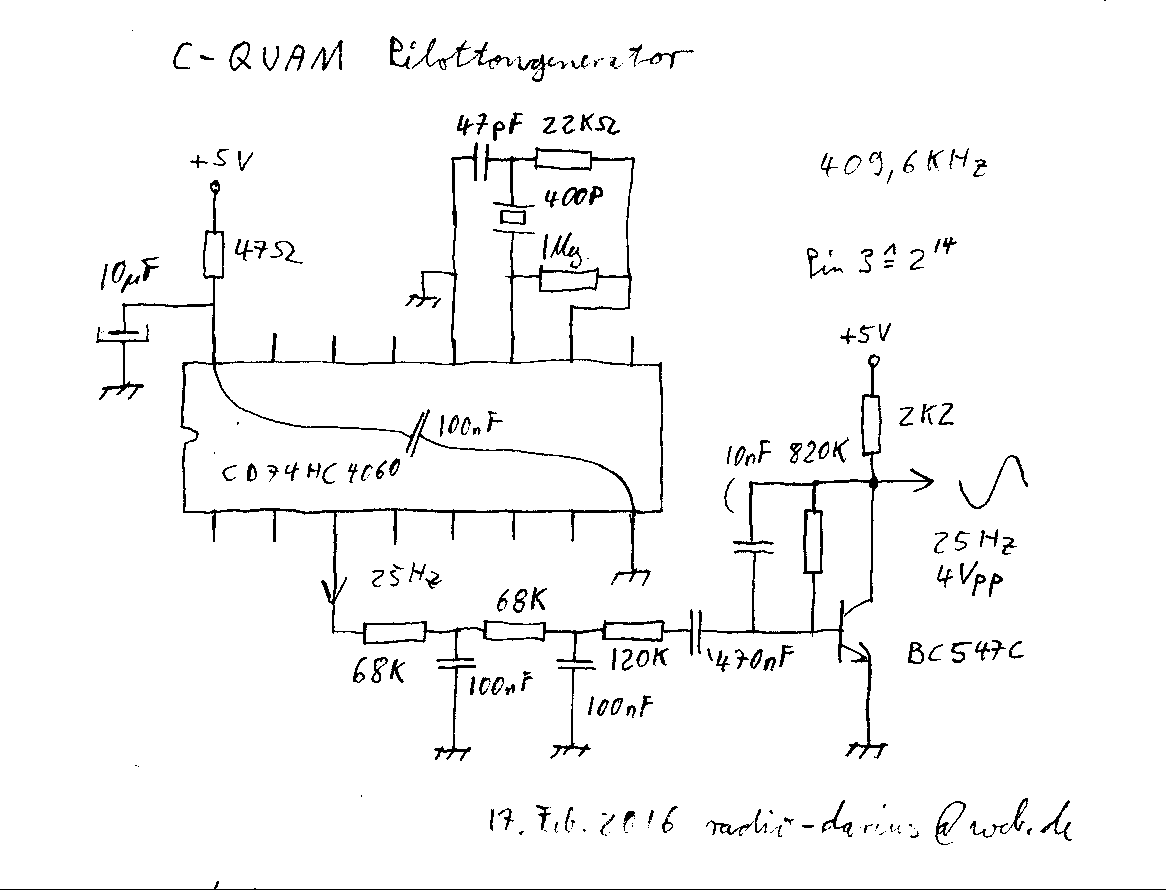
To produce the 25Hz pilot tone, I use a 400P ceramic resonator in combination
with the CD74HC4060. This makes the pilot tone generator free of any
adjustment.

At Pin3 is a square wave signal with 24.7Hz. Three low-pass filters form a sine wave and a transistor brings the level to about 4Vpp.
Workupload Pilot sound
processing LTspice
The sinusoidal shape suffices for
the purpose. Since it is coupled to the Q-modulator via a high-resistance
(100K), a coupling capacitor is superfluous.
The CD74HC4060 with its ceramic
resonator is shown at the bottom left. Under the IC are still parts in the
version since I had little space. The transistor on the upper right belonged to
an RC phase shifting generator, now it makes the sine shaping for the 25Hz
pilot tone.
Note that the pilot tone is included in the sideband, which is in quadrature to
the carrier, as an under listening frequency with 6% -10% modulation degree.
The stereo display on the receiver is not switched on by a simple amplitude
modulation.
Carrier preparation: quartz oscillator, differential signal Q modulator and
limiter amplifier:
In order to achieve high frequency
stability, I use a quartz. I have made this one.

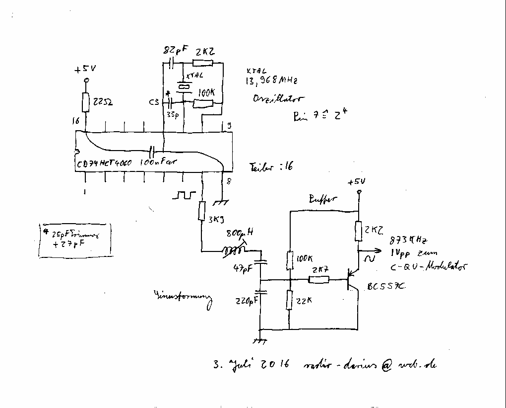
The XTAL oscillator is built with
the CD74HCT4060. At Pin 11, a trimming capacitor is installed for accurate
tuning of the frequency. At pin 7, the quartz frequency, divided by 16 and
rectangular, appears. A series circuit is used to couple a filter circuit,
which draws the first harmonic oscillation from the square wave signal. A
capacitive voltage divider provides the now sinusoidal carrier oscillation with
the appropriate amplitude to an emitter follower, which provides it with
low-impedance buffering for further processing.
C-QUAM Modulator
Do the phase modulation like
Steudler described in section 4.7.2 page 15 of 18. Via R3, the buffered
oscillator voltage arrives without phase shift and unmodulated to the collector
of Q1, the Q modulator.
At the base the oscillator voltage is in quadrature. C4 of which Xc = 33K and
the basic voltage divider of R1 in parallel R4 together 776 Ohm push the phase
by almost 90 degrees and divide the voltage to the required value for
linear control of the transistor in the emitter circuit. Since the slope is
proportional to the emitter current, the oscillator voltage appears in
quadrature and with the L-R difference signal plus pilot tone
amplitude-modulated on the collector. Both these add up and give the QU carrier
signal superimposed with a difference signal and pilot tone.
The high pass from C2 and R6 removes
the low frequency and the limiter amplifier in the 4046 the AM residues. The
C-QU carrier is connected to the output of the limiter amplifier. The sine
shape of the HF is very important in this case, so that no pulse width
modulation occurs after the limitation, from which an undesirable amplitude
modulation results.
Tip: Via pin5 to 16, inhibit, the unused stages of the 4046 can be switched off
except for its limiter. Pins 3, 8 (GND) and 9 are connected. Pin14 signal in
and Pin2 out. The remaining pins remain unconnected.
Via R7, the L-R difference signal is coupled with C6 to the emitter of the Q
modulator. C5 does not cut the frequency response, but blocks the HF. Its
optimal value I have determined with LTSpice. For the low frequency, this is a
basic circuit. This does not rotate the polarity of the phase modulation.
The pilot tone is galvanically coupled to the Q modulator via the resistor R13.
The modulation degree of the pilot tone mPilot can be calculated: With 100%
channel separation, the difference signal level is 4Vss, as is the pilot level.
mPilot = R7 / R9 = 8K2 / 100K = 8.2%
Workupload C-QU carrier processing LTspice
A few important points:
One of the most important inventions of MW-Broadcast Technology is the channel grid. It allows interference-free reception with a high audio bandwidth at the same time by the use of notch filters in the receiving devices. Quartz stable frequency processing is therefore a must. A frequency in the MW channel raster is e.g. 720KHz. In Europe, the channel spacing is 9KHz. Subtract or add always 9KHz from the 720KHz to find a suitable frequency for your transmitter. There are also PLL kits on the net.
When using FM radio as a source, please take care that the 19KHz pilot tone, MPX and RDS are carefully removed from the low frequency.
Last update August 24, 2016 14:14 CET
Posted before 23rd October 2015 by oldeurope
Saved from http://c-quam.blogspot.gr/2015/10/c-quam-pruefsender.html Saturday, October 14, 2017