The term "Carrier-Current" originated in the 1920s when the telephone industry developed methods for transmitting several conversations over a single pair of wires at the same time. The telephone industry used special lines specifically designed for the purpose.
Electric power companies soon discovered that they could use the same techniques utilizing their existing high-tension power lines. This enabled power companies to communicate between central offices and sub-station switching facilities with their own private telephone systems. The technique was further developed to provide remote control of unattended sub-stations. A "carrier" frequency far below that of the standard broadcast band (AM) frequencies was used to avoid interference. The lower carrier frequency also permitted greater range of communications.
By the late 1930s the telephone industry developed other means of transmitting simultaneous messages over long distances. The use of Carrier-Current was dropped from use as far as telephone companies were concerned.
Also in the late 1930s radio hobbyists became interested and began experimenting with two-way stations. Carrier frequencies were kept between 150 kilohertz and 200 kilohertz to avoid interference with power company communications and Standard Broadcast Band. Interest became quite intense in the early 1940s because Carrier-Current communications was the only form of radio allowed to hobbyists during the World War II years. [pdf]
With Carrier-Current techniques fairly well established it was only natural that radio hobbyists would want to simulate commercial broadcast stations. During the late 1940s several Eastern colleges began broadcasting to the campus and to the dormitories. The idea quickly fired the imagination of radio enthusiasts at other schools and colleges, and even small towns and church groups. Here was an ideal "closed circuit" system that could bring news and other information to a small group of people. In rural areas a simple 25 watt transmitter, coupled to the community power lines, provided a range of up to 5 miles. City ranges however were limited to about 1 or 2 mies because of the greater "loading" of the power lines by lighting, appliances, motorized machinery, etc. The carrier frequency used was selected from the Standard Broadcast Band so that reception was possible with any standard AM radio.
At first I tried the normal method of connecting the LPB coupler directly to the AC line at the fuse box, and found the signal just didn't get out that well, it was weak in the street. 'Neutral loading', that is sending the signal into the neutral wire of the power grid, was even worse, likely because I didn't have the separate earth ground system needed to use it properly.
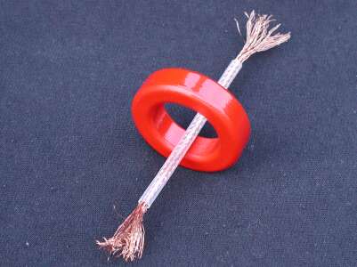
I'd been thinking of ways to inductively couple to the line, instead of a direct connection. If it could work it would be much safer than connecting to the line, and maybe even simpler too. In radio work I use ferrite as core material in radio frequency transformers, and some of those have one turn windings on the low impedance side. In a ferrite donut core, a wire just has to pass through the hole to be considered a turn.
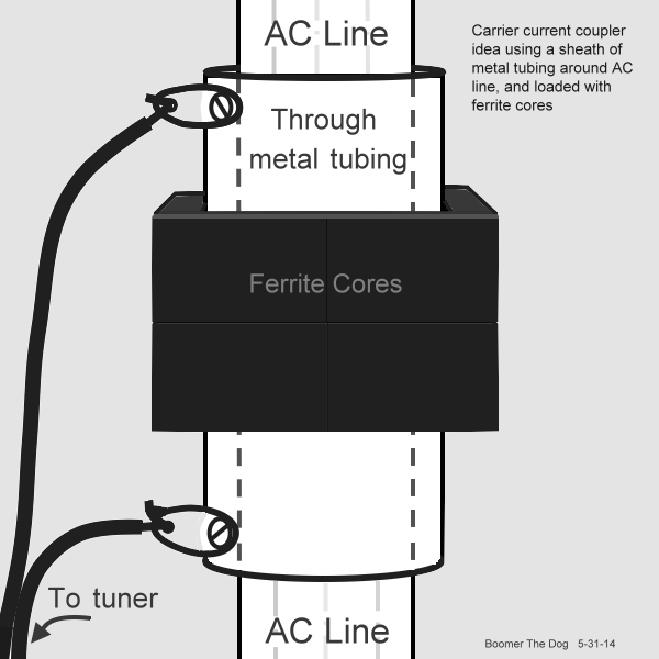
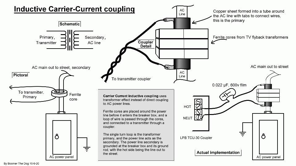
Extending this idea to carrier current, what if we could put a ferrite core around the power line, making the power line become our one turn secondary, then loop a second wire through the core as the primary, and connect that to our transmitter tuner?
We need a split core large enough that it can fit around the line, with some room to spare for the primary loop going to the coupler, and where the two halves of the core can be clamped together. This could be bought from a magnetics company on line, but one recycled source of ferrite that will work is older CRT monitors and televisions. The core is in the flyback transformer, that's usually in a large shielded area and provides many voltages for the circuits.
With careful removal, the cores will look like this. It's not a torus donut shape any longer, but it's still a ring of magnetic material, which is what we need for our project.
Here's the first coupling method I tried with the ferrite core, a simple transformer method with the primary having several turns of speaker wire, and the secondary being the power line itself, as a single 'turn' through the core.
I tried it different ways, more turns on the primary and fewer, stacking more cores, and gapping the cores because they were heating up. Here are some early tests.

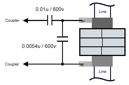
The transmitter feeds the coupler, which is a tuner for the power line, and it also isolates the transmitter from the line. The coupler feeds the blue loop primary, the secondary is the power line.
How does this work? Well, the ferrite core, along with the tuning action of the coupler, splits the AC line into a hot side and a ground side, at the station's frequency. The hot side is the section of line going to the pole, where the AC service is coming in from. The ground side is the breaker box and its grounds, plus all of the house wiring. My breaker box has 3 ground connections, one to the water main where it comes through the wall into the basement, and two ground rods outside with ground wires leading out to them. That appears to be a decent deep-buried ground.
Note that my system is feeding the radio signal to all three of the lines coming in, two hots and the neutral, in parallel. That's contrary to the usual coupling practice of feeding the signal between the neutral and hots. It seems to me that with transformer feed, the signal would be split 3 ways, to both phases and neutral. If the signal in the hots is stopped at a power transformer on a pole somewhere, the signal on the neutral has a chance to continue on, since there are usually longer runs of unbroken neutral lines in a neighborhood than hots.


Click for larger worksheet in new tab
The ferrite cores would saturate easily and heat up, and positive modulation peaks were being flattened, so the cores were "gapped" with paper between the pole pieces. Small paper squares were taped to the poles, then the cores were clamped back together.

I want to find out what kind of ferrite material is used in the cores, then find something better in a large split-core design that will fit around power lines, allowing anyone to benefit from carrier current in this way.
