 Try this circuit out for yourself, it's made especially to generate a pilot tone used in the C-QUAM AM stereo system, but could be used in other projects that call for a sine wave in the audio frequency range. Status: Working, but not applied to a C-QUAM transmitter yet.
Circuit Diagram

View bigger
Instead of being fed from the discharge pin 7 as in the usual astable 555 oscillator, pins connected to output pin 3 instead.
Oscillator on protoboard
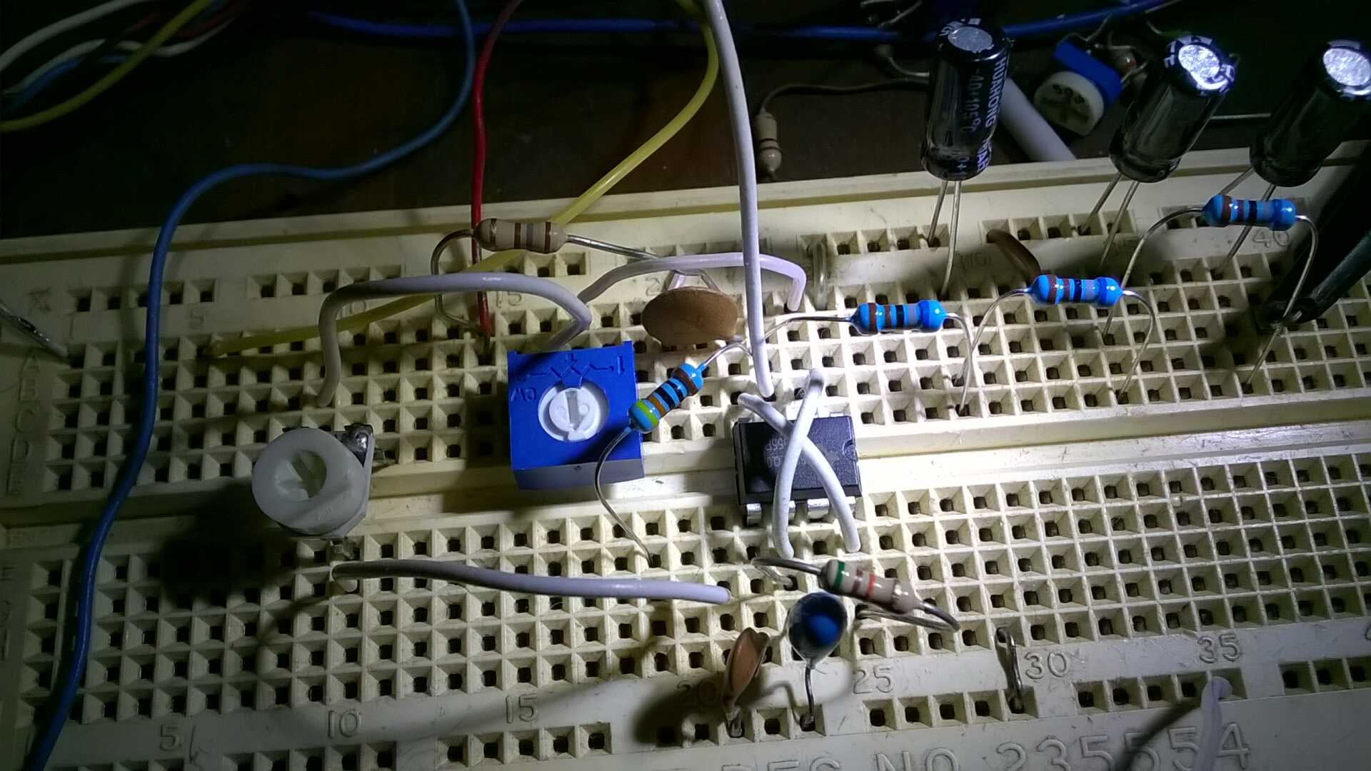
View bigger
Scope Trace
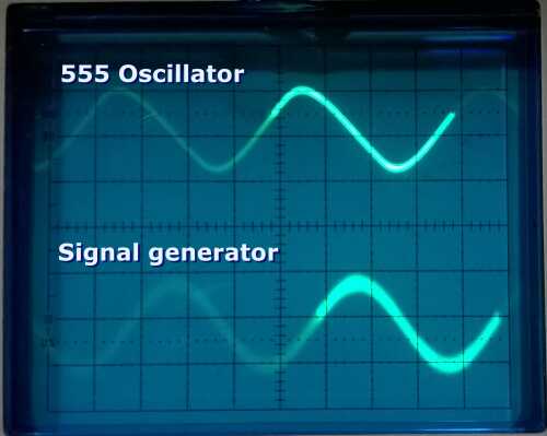
The top trace is the 555 oscillator after filtering. The bottom wave is from a digital signal generator card.