Building an AM Stereo Transmitter
The AM Stereo exciter described in these pages is a low powered transmitter
that includes equalization similar to what called for in NRSC-1. Although
the design is not FCC type-accepted, testing of my prototype unit has shown
that there is very little interference to the second-adjacent channels
(frequencies 20KHz to 30KHz from the carrier). Spectrum analyzer measurements
have shown that emissions in this frequency range are at least 55 decibels
below the carrier.
Another important feature of this design is the three-band peak limiter.
This is a circuit that prevents overmodulation without introducing excessive
distortion. Limiters are important to obtaining a loud but clean on-air sound.
A broadband limiter or a two-band limiter could be used in place of the three
band limiter. Both of these circuits are simpler, but they may display more
noticeable idiosyncracies than the the three-band design.
Frequency control is done by means of an AT-cut quartz crystal oscillator.
Custom-cut crystals can be purchased from companies such as Jan Crystals or
Crystek for less than US$15.
More Detail
The schematics for this transmitter are divided into several sections, as
shown in the block diagram.

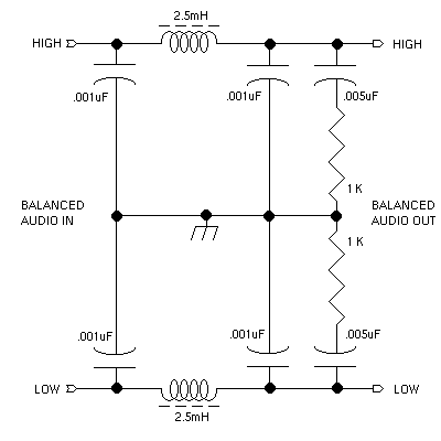
Following the diagram, we see that line-level left and right audio passes
through an LC lowpass filter. The purpose of this LC filter
is to attenuate any RF that may be present at the audio inputs. This can
occur if the exciter is used in the presence of strong electromagnetic fields.
The 0.001uF capacitors and 2.5mH choke form a filter that begins rolling off
around 140KHz with a slope of 12dB/octave. AM band signals riding on the
audio will be attenuated by at least 20dB. The 1K resistors and 0.005uF
capacitors provide an appropriate terminating load for the filter at radio
frequencies.
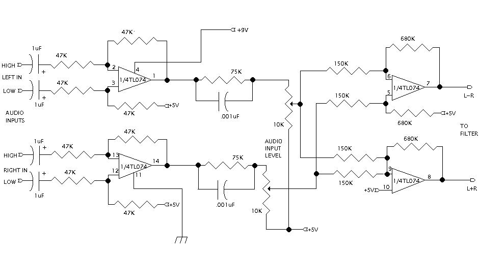
This stage is centered around a single TL074 (or similar) quad operational
amplifier IC. Two of the op-amps are configured as unity gain difference
amplifiers. They convert the balanced inputs to unbalanced audio and null out
common-mode noise or hum that might be present on the inputs. The left and
right channel audio then goes to pre-emphasis networks, which consist of
a 75Kohm resistor in parallel with a 0.001uF capacitor and a 10Kohm
potentiometer. If a 10K ohm potentiometer is not available, a 25K or 50Kohm
unit could be used, but a resistor would need to soldered in parallel with it
so that the resistance between the two ends of the potentiometer is 10Kohms.
The two op-amps following the audio level potentiometer form the L+R/L-R
matrix and provide gain to compensate for the losses encountered in the
pre-emphasis circuit. From this stage on, all audio is L+R/L-R, as opposed to
left and right.
The lowpass filter consists of three filters, two Sallen-Key lowpass filters
and a Twin-Tee notch filter. The Sallen-Key filters begin rolling off slightly
above 10KHz, and the notch filter is tuned to approximately 14KHz. The
trimmer potentiometer in each of the two notch filters is intended to
compensate for small mismatches in the component values in the filters. These
trimmers are adjusted to maximize the depth of the notch. The
combined frequency response of these filters is one that starts rolling off
gently near 10KHz and rolls off rapidly in the 11-13KHz region. A small
lobe does appear above 15KHz, but it does not contribute significantly to
splatter, according to tests. 44KHz components from CD audio are attenuated
enough that I was not able to detect them during spectrum analyzer
measurements nor with conventional receivers tuned 44KHz away from the carrier.

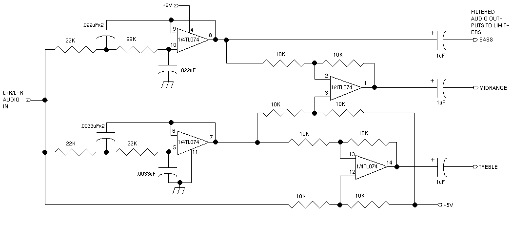
After the audio has been pre-emphasized, mixed to L+R/L-R, and low-pass
filtered, it is split into three frequency bands. This crossover forms the
input section of the three-band limiter. For more information on how multiband
limiting and compression work, click here.
The crossover consists of two Sallen-Key lowpass filters with different
cutoff frequencies and two difference amplifiers. The filter with the lower
cutoff provides the low band output. The mid and high bands are derived by
subtracting the outputs of the two filters and by subtracting the output of
the filter with the higher cutoff from non-filtered audio.
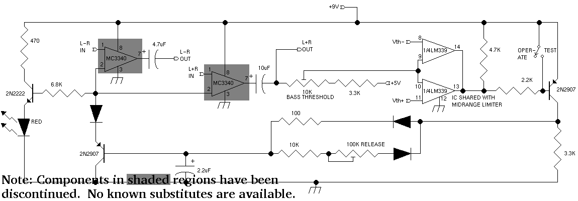
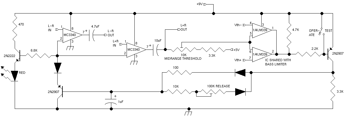
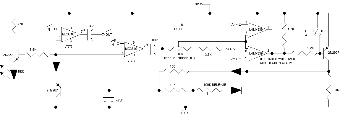
The peak limiters in this exciter respond to the peak amplitude of the L+R
audio and simultaneously adjust the gains of the L+R and L-R signal paths.
Each limiter consists of two comparators that monitor the peak amplitude of the
L+R output. The LM339 uses open-collector outputs, which allows the outputs
of two comparators to be safely tied together to build a window comparator.
In these limiters, one comparator triggers on negative peaks, whereas the other
triggers on positive peaks. When either comparator is triggered, the node
formed by the outputs of the comparators and the 4.7Kohm and 2.2Kohm
resistors is pulled low. This turns on the 2N2907 transistor, which, in turn,
charges a capacitor through a diode and a 100ohm resistor. The voltage on this
capacitor controls the gains of the two MC3340 voltage controlled amplifiers.
The 100 ohm resistor causes this capacitor to charge very quickly, but the
discharge rate can be controlled by adjusting the 100Kohm trimmer. The
other 2N2907 serves as a voltage follower, and the diode connected to its
emitter performs level shifting. Gain reduction in the MC3340 amplifiers
begins to occur when the voltage on the gain control pin is about 2volts.
Around this voltage, the combined voltage drop of the red LED and the
base-emitter junction of the 2N2222 is exceeded, and the LED glows.
Bass Limiter
Midrange Limiter
Treble Limiter
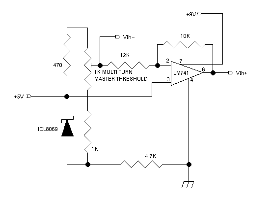
This circuit supplies reference voltages to the comparators in the limiters.
These reference voltages are derived from an ICL8069 voltage reference IC,
which provides a 1.25 volt output that is relatively independent of temperature.
If this IC is not available, two series-connected silicon diodes could be
substituted. The 741 operational amplifier generates a positive reference
voltage that is 83% of the negative reference voltage. The gain of this stage
is selected so that when negative modulation peaks are limited at 100%,
positive modulation peaks will be limited around 120%.
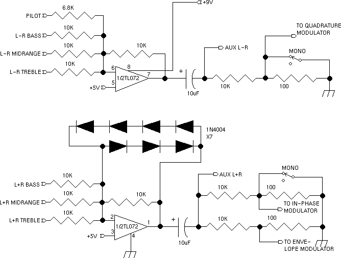
The outputs of the limiters are combined here. The L-R channel has an extra
input for the pilot tone. The resistor values selected set the pilot level
around 5%. Auxiliary outputs are provided to drive other transmitters or
for monitoring purposes. An oscilloscope connected to the L+R output and
to the RF output, for instance, could be used to observe trapezoid modulation
linearity patterns.
The diodes in the feedback loop of the L+R combiner cause this stage to
function as a soft clipper to catch limiter overshoots. Gentle clipping
significantly improves average modulation levels without introducing audible
distortion. Since the diodes were not part of the original design, these
diodes had to be added to the foil side of the cicuit board in the prototype.
The Web page layouts will soon be updated to include clipper diodes on the
component side. Three diodes were found to effectively limit overshoots to
100% modulation. The three series diodes clip negative peaks, while the four
diodes let the positive peaks ride at a slightly higher level before clipping
occurs.
The quadrature AM signal is generated here. The frequency reference is a
crystal oscillator operating at four times the desired broadcast frequency.
The crystal should be parallel resonant, with a load capacitance of 18 to 32 pF.
A trimmer capacitor is placed in series with the crystal to allow trimming of
the broadcast frequency. The first 2N2222 is connected as a Colpitts
oscillator, and the second 2N2222 serves as a buffer and amplifier to drive
the 74LS74 flip-flops. The flip-flops are connected as a walking-ring counter,
which divides the frequency by four and provides outputs that differ in
phase by 90 degrees. The TTL outputs are attenuated and then fed to a pair
of NE602 balanced mixers. The 220Kohm pull-down resistor present at pin 2 of
the "I" mixer causes this mixer to behave as an AM modulator, rather
than as a suppressed-carrier modulator. Pin 1 on this IC will be about 13.5mV
more positive than pin 2. Thus, 13.5mV is the reference level that corresponds
to 100% modulation. The NE602 outputs have an impedance
of about 1500 ohms, so they can safely be tied together. At this point, the
harmonic content will be very high because the carriers supplied to the NE602s
were a square waves. In order to produce clean stereo, the QUAM signal
reaching the limiter must be sinusoidal. The filter at the output of this
stage attenuates harmonics of the carrier and does not require tuning for
small changes in broadcast frequency. The component values, however, depend on
which area of the band the broadcast frequency lies:
For operation from 530KHz to 800KHz, use the "Low" values
for operation from 800KHz to 1150KHz, use the "Mid" values
for operation from 1150KHz to 1710KHz, use the "High" values

Limiting is performed using an inexpensive NE592 video amplifier and two
silicon diodes. The NE592 is configured for about 40dB of voltage gain by
shorting pin 12 to pin 3. More gain could be achieved by shorting pin 11 to
pin 4 instead, but experiments showed that when the latter is done, some
incidental phase modulation is impressed upon the carrier. The output of the
NE592 is then fed, through a 2.2Kohm resistor, to a pair of silicon diodes.
The diodes enhance the limiting action of the NE592 and attenuate the carrier
to a level appropriate for the NE602. The final NE602 receives L+R audio that
amplitude modulates the carrier. It should be noted that to operate in mono,
audio to the two modulators ahead of the limiter is muted. Audio
to the NE602 in this stage is never muted. The output of the NE602 passes
through an LC lowpass filter to attenuate harmonics. Component value selection
works the same as for the previous stage. Following this filter are two
stages of voltage amplification, with gains of 13dB and 19dB, for a total of
32dB. The final stage is a push-pull voltage follower consisting of a 2N2222
and a 2N2907. The purpose of the voltage follower is to allow the exciter to
drive low impedance loads without a significant drop in output voltage. The
two silicon diodes between the bases of the transistor form the biasing
network, and the 4.7ohm emitter resistors stabilize the DC quiescent current
flowing through these transistors.

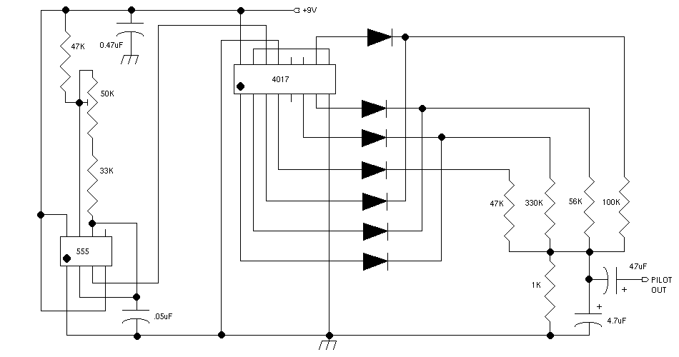
The pilot tone generator produces a 25Hz tone, at a modulation level of about
5%, to trigger stereo detectors in receivers. A 555 timer is used in an
astable (oscillating) mode to produce a 200Hz square wave. The 4017 decade
counter divides the frequency of the square wave by 8. The decade counter
sequentially pulls each of its 8 active output lines high for 1 period of
the 555's 200Hz square wave. The output pulses from the 4017 drive a
resistor/diode network that produces a stepped waveform approximating a sine
wave. A 4.7uF capacitor smooths out the stepped waveform.
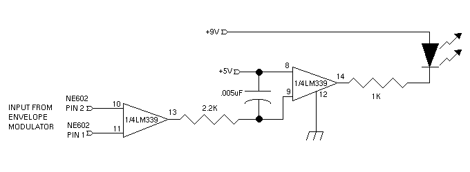
The overmodulation alarm circuit indicates the presence of negative modulation
peaks in excess of 100% by flashing an LED. Normally, pin 1 of the envelope
modulator IC is more positive than pin 2. Negative peaks exceeding 100% will
cause pin 1 to become negative with respect to pin 2. The first comparator in
the alarm circuit detects this condition, and its output assumes a low
impedance, thereby charging up the 0.005 uF capacitor connected to the inputs
of the second comparator. The voltage on this capacitor causes the second
comparator's output to assume a low impedance, thereby lighting the LED. The
input impedance of the second comparator, which is several megohms, serves
as the discharge path for the 0.005 uF capacitor.
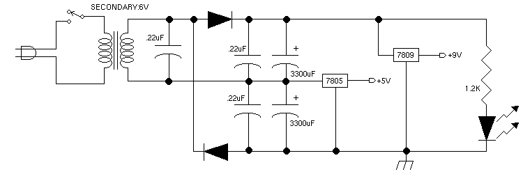
The power supply provides regulated outputs of 5 and 9 volts to the various
stages in the exciter. The 5 volt supply doubles as a virtual ground for the
operational amplifier audio stages. Total current drain from the 6.3VAC
transformer will be approximately 300mA. Another hobbyist reported that a
simplified version of the design, consisting only of the modulator circuits,
output stage, pilot tone generator, and an op-amp, draws as little as 50mA DC.
An alternate power supply is shown here.
This is the power supply used in the prototype unit. The extra chokes and
capacitors in this supply help to attenuate power line noise and spikes.
The crystal oven keeps the crystal at a constant temperature for optimum
frequency stability. The crystal oven used in the prototype unit has a heating
element with a resistance of 10 ohms. A 1.2 Ampere, 6.3 volt filament
transformer was used in the supply. The choke, resistor, and capacitor
connected to the crystal oven thermostat help to suppress oven turn-on and
turn-off transients that otherwise cause audible "pop"s in the signal.
Using a fuse, which is not shown in the original schematic, is always a good
idea.
Assembly Instructions
Back to Exciter Page
Compiled as a single document by Boomer The Dog, August 2016


